The article is inspired by the course I took called “Testing without requirements”. During the training, test engineers were taught how to identify what information about a product was missing, analyse the reasons behind it, and recover the requirements using a variety of different techniques.

I’m not going to discuss the terminology or any specific processes around the “reconstruction” of requirements. Instead, I’d like to show you how to determine whether you have all of the necessary information for proper testing of your product, and how to identify which areas should be prioritised when looking for any missing details.
Part 1 covers the requirements concerning the product’s composition, functionalities, and external interfaces, whereas Part 2 gives a rundown of the product’s qualities.
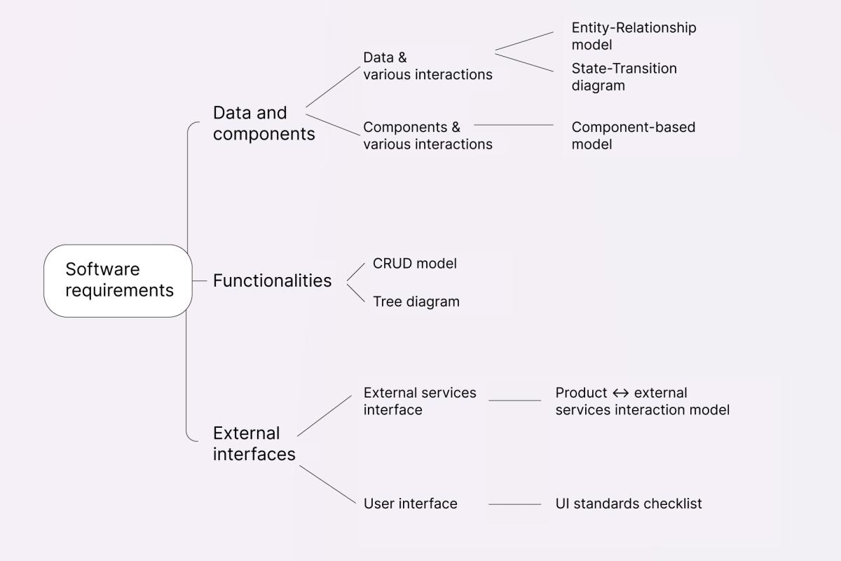
You can use the tree diagram below as a checklist for a comprehensive assessment of any product, or as a short introduction to the first part of this article:
Data and components
Product’s composition based on data
When looking at the product’s composition from a data perspective, we’re going to consider two aspects:
- static – What are the entities that exist in the system? How do they relate to one another? What are their attributes?
- and dynamic – How do the states of these entities change?
Entity-Relationship model
Let’s start with the static aspect. The image below represents a static model called Entity-Relationship model – essentially, you can use it to describe something through entities, relationships between them, and their attributes.
An entity is a set of objects with common characteristics. In other words, an entity is something abstract, while an instance of that entity is a single, specific object within that abstract group. For example, A23Zn5 is an instance of the entity Booking. As such, it basically replicates the principles of object-oriented programming, where entity = class, instance = object, and relationship = method.
Entities are connected to one another in a multitude of ways – both in the real world and in the system. All these connections are shown in the model as relationships (relational approach). In turn, the relationships can be of 3 types: one-to-many, many-to-many, or one-to-one.
Entity-Relationship model creation algorithm:
- Identify all entitites,
- Define all attributes of these entities,
- Identify all relationships between the entities.
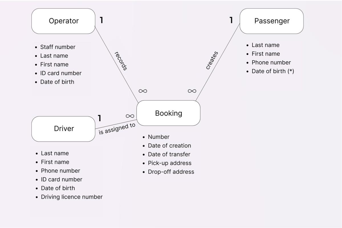
Although the model may look a bit bulky at first, it actually makes it much easier to get a good understanding of the system. For example, in the picture below Booking is an entity, Number, Date of creation, Date of transfer, etc. are its attributes, and Is assigned to is a one-to-many relationship:
Finding missing information using the static Entity-Relationship model
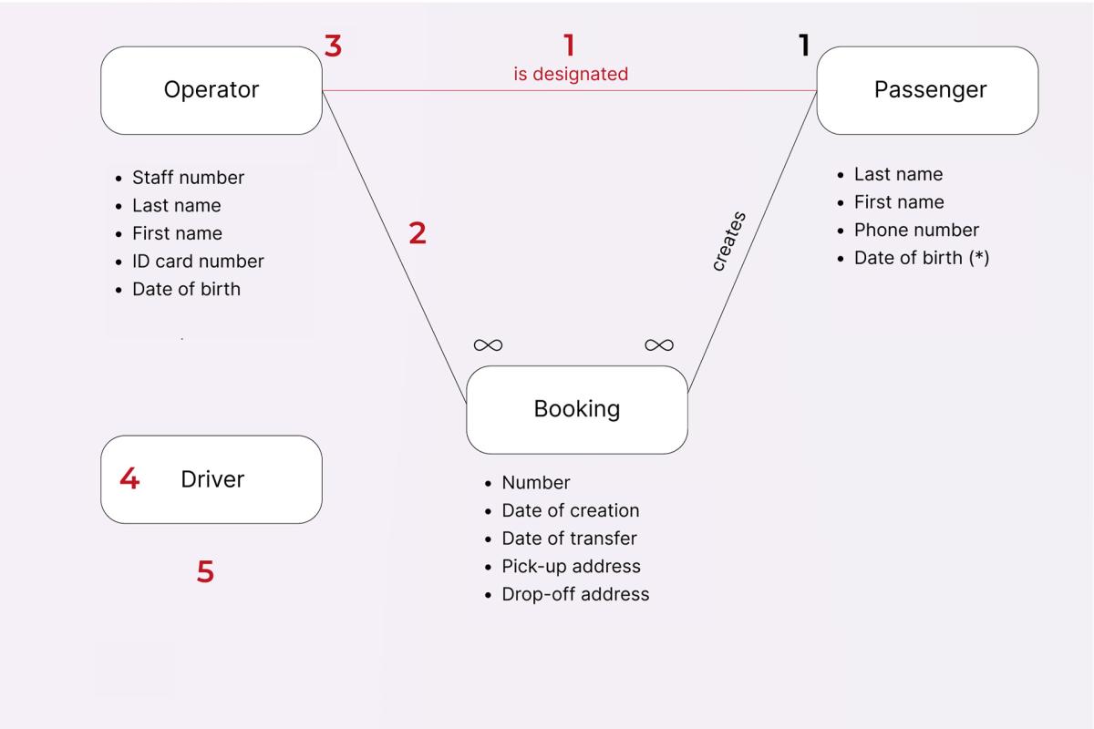
It’s important for all of us to know what kinds of mistakes might be made when creating the Entity-Relationship model. So, here’s a list of things that you should look out for, along with an image to demonstrate what each mistake can look like in practice (positions in the list correspond to numbers in the picture below):
- Duplicate relationships (although it may be normal in certain cases, you should always make sure that it’s not reduntant);
- Unspecified relationship – a relationship that is not identified in any way, and therefore, has no value to the team (determine what the connection is);
- Relationship without a type – once again, the relationship is not fully identified, which means it’s of no value to the team (determine which of the 3 existing types is at play);
- Entity without any relationships (sometimes it may be okay, however, in most cases, it’s a sign that there’s actually something missing in the product’s documentation);
- Entity without any attributes – if an entity has no specific properties/attributes, then how are you supposed to identify an instance of such entity? (For example, both Smith and Williams are instances of the Driver entity based on their attribute Last name);
Circular reference. In the case of a circular reference, two entities refer to one another, thus creating an error. Sometimes, though, it may work perfectly fine, but even then, it is still quite difficult to test such references properly – which is why it’s strongly recommended to avoid them altogether.
State-Transition diagram
Now, let’s move on to the dynamic model, called State-Transition diagram – it illustrates different states of an entity, as well as various conditions that trigger transitions between certain states.
For example, you can draw a diagram for the entity Booking that looks something like this:
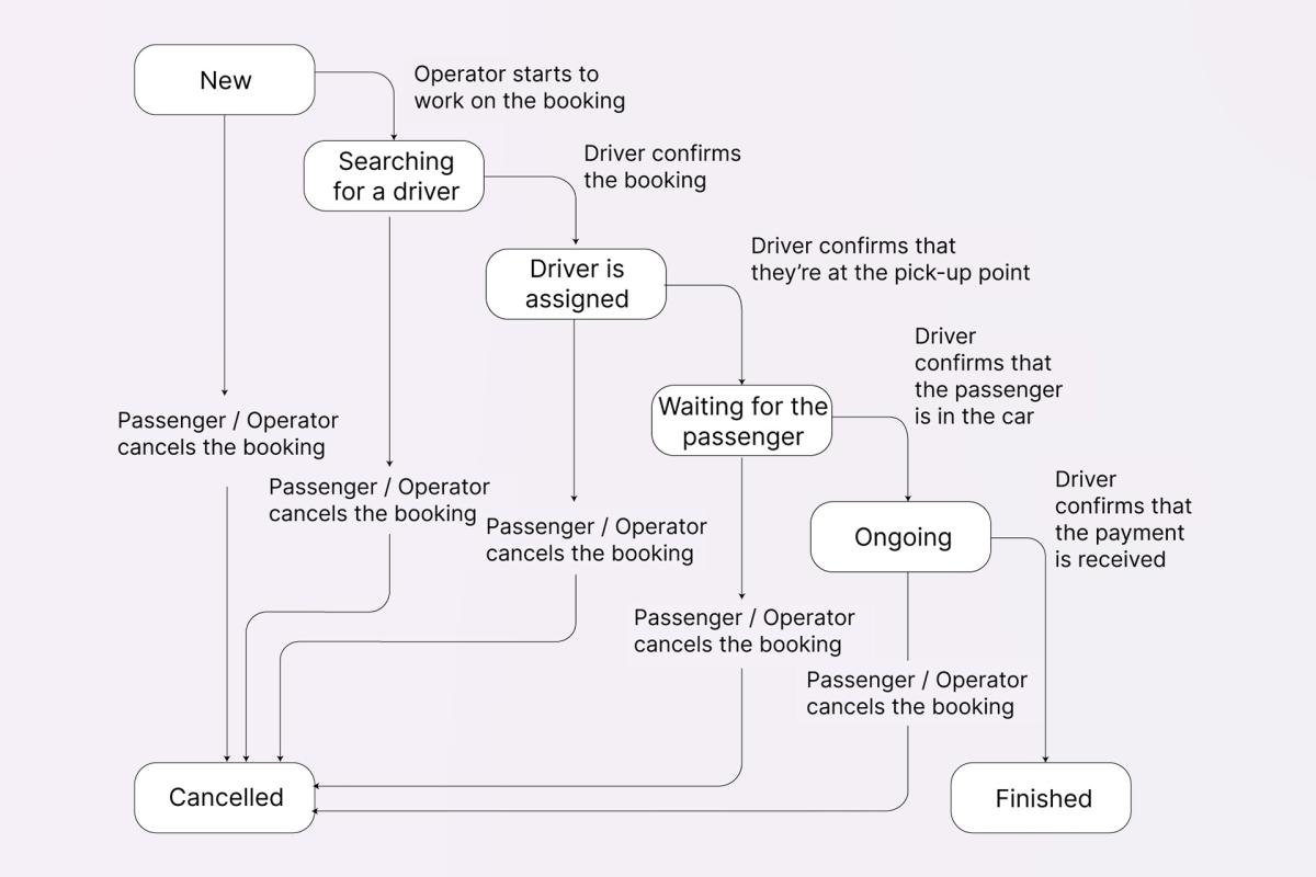
Boxes show all the different statuses (aka states) that a booking can have, arrows indicate transitions from one state to another, and the comments next to them specify event triggers.
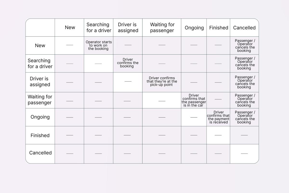
First, you should map out the main scenario, and then begin to investigate the alternatives, checking whether all of the states are actually possible. To make sure you don’t forget anything, you can create a table of states and transitions as sort of an aid: use it to verify all action sequences and their combinations, highlighting the cells that may be ambiguous or require further clarification.
Finding missing information using the dynamic State-Transition diagram
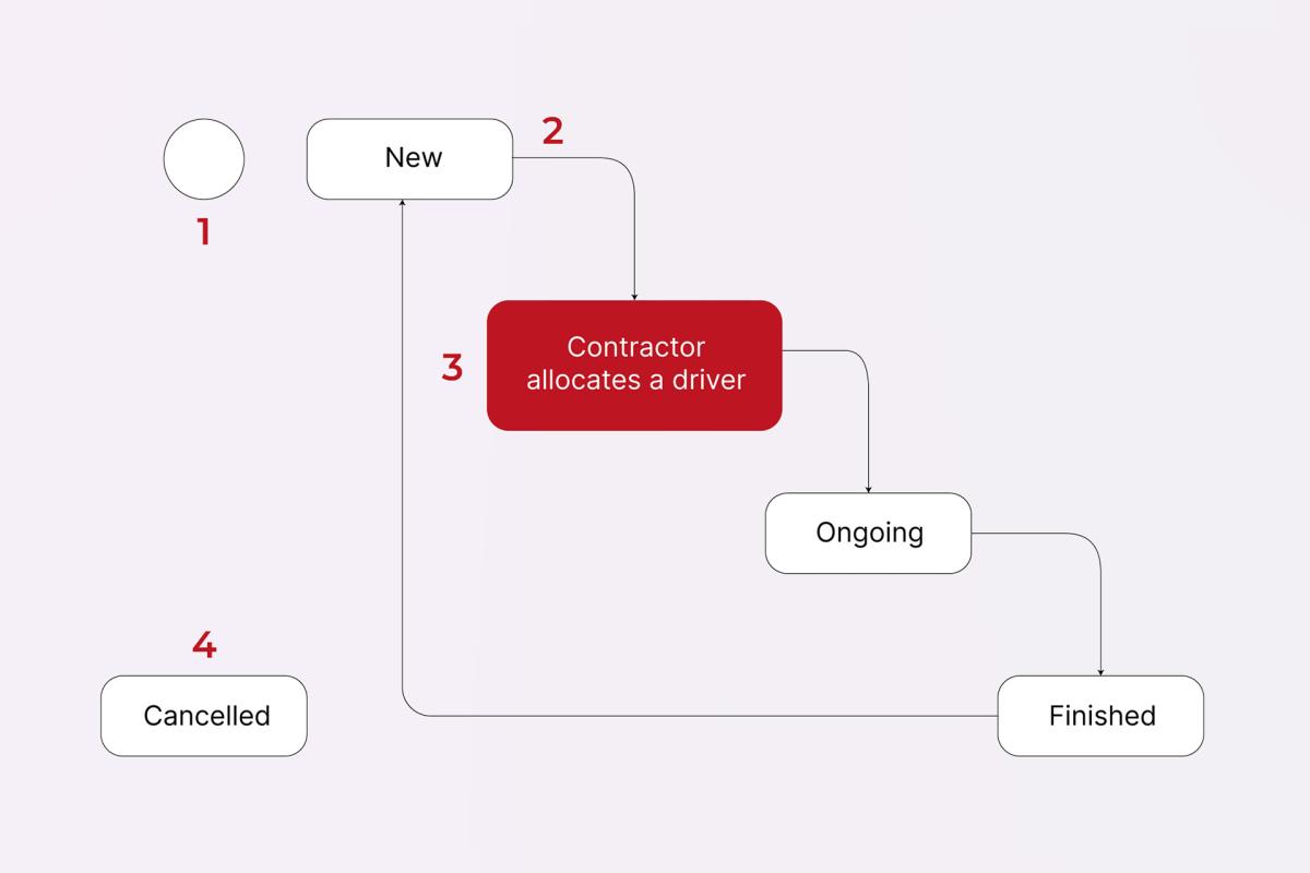
What mistakes might you make when creating a State-Transition diagram? (Just like in the previous list, positions here correspond to the numbers in the picture underneath):
- Initial state not identified (either draw a standalone point, or colour in the box representing the initial state);
- Unspecified event triggers (determine what they can be);
- States are related to different entities (say the entity’s name aloud, along with every state in the diagram, so that it’s more apparent which of the combinations don’t make sense);
Isolated states with no entry/exit points (find all existing connections).
Product’s composition based on components
When you want to look at the system’s composition from a components perspective, you need to answer the following question: What subsystems, modules, blocks, etc. make up the entirety of your product?
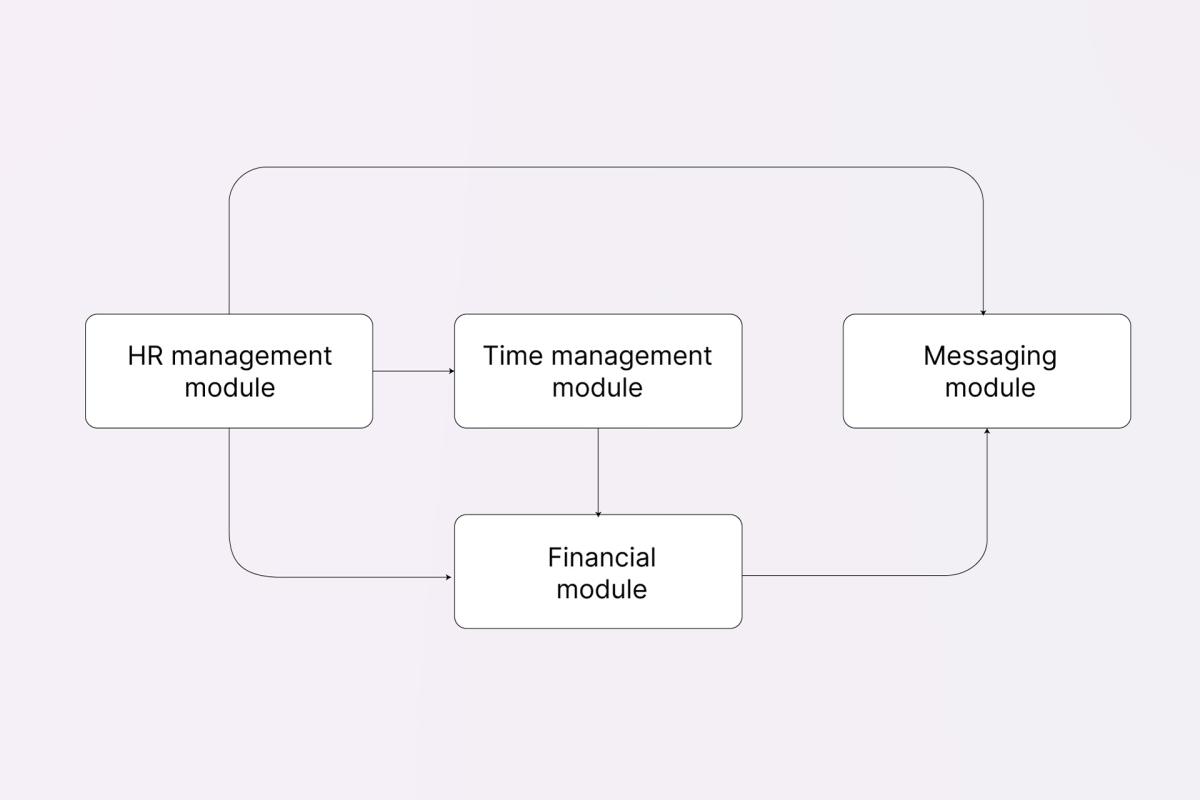
For example, Noveo has an internal platform for employees – the portal consists of multiple modules, but for now we’re going to consider only 4 of them:
- HR management module – for working with employee data,
- Time management module – for logging time spent on tasks,
- Financial module – for generating various financial documents and reports,
- Messaging module – for sending out reports, emails and notifications to users.
Like so, our system’s structure can be represented as in the image above, but your team can use whichever diagram you see fit for each particular project.
Why is this model necessary for testing? Because it helps you to understand:
- where certain data is being stored and/or managed,
- how data “moves” from one component to another,
- and whether any external systems are involved in the process.
Functionalities
What can your system do?
In order to determine which features weren’t potentially included in the documentation, you can create a functionality-based model of a system. For this, let’s first look at 2 types of models, both of which can help you visualise the same kinds of information, but in pretty different ways.
CRUD model
CRUD is an acronym of Create, Read, Update and Delete – you can draw parallels between these commands and HTTP methods Post, Get, Update, Delete.
For each entity and relationship, you should describe:
- how it’s created,
- how it’s called/displayed/viewed,
- how it’s edited/modified/updated,
- how it’s deleted.
To get a better idea of this model, let’s take a look at a social media platform of your choice and create a CRUD table for the entity User and the relationship Friends (or Subscriptions, Followed accounts, etc.):
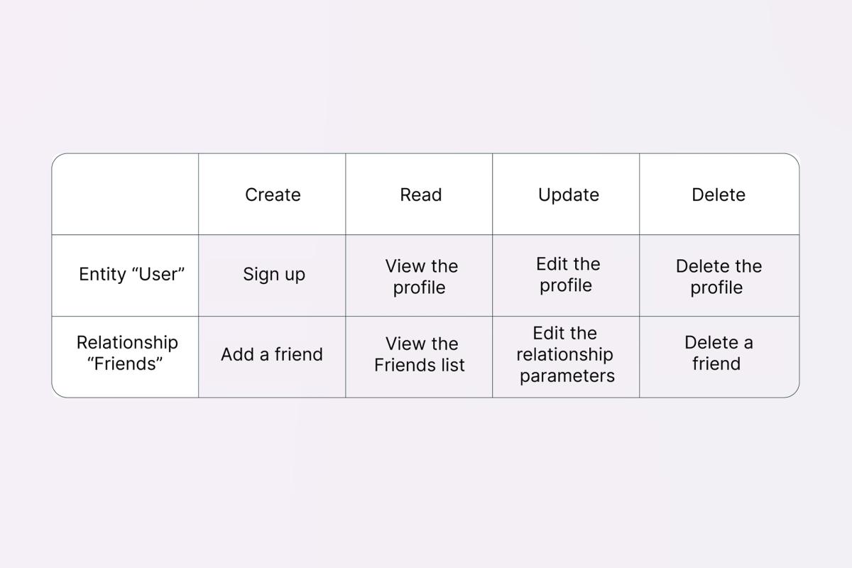
Once it’s done, you should analyse the requirements document and find a scenario for every single action represented in your CRUD table.
But, what if you tried and didn’t manage to find certain scenarios? First, highlight the cell in question or put a question mark next to it, and then – you guessed it – ask the team and clarify whether the scenarios you’re looking for were omitted unintentionally, or maybe they shouldn’t have been there to begin with (it sounds strange, but it does happen sometimes too).
Tree diagram
Another model you can use to visualise the features of a system is a tree diagram, with its branches representing decomposed functionalities.
To start, write down all big logic groups (you can separate them by modules or entities), after which, decompose them into smaller chunks – subgroups, functions, etc. You can use the image below as a reference:
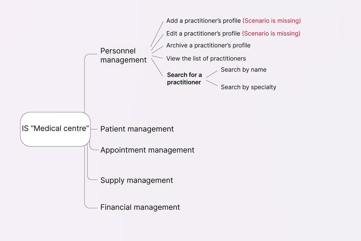
Here, a large Personnel management module is broken down into multiple functionalities (including CRUD commands as well as other actions), and each functionality – into several sub-functionalities (as is the case with Search for a practitioner).
It is important that every end of the outermost branches have a corresponding description in the product’s documentation (How is it done? What is its purpose? What is the expected outcome?). If some of this data is missing, make sure to bring it to the attention of your team members and eliminate the gaps together.
External interfaces
How does your product interact with the outside world – with its users, other systems, etc.?
Product <-> external services interaction model
When creating this model, don’t just name all third-party services – ensure that you also identify what kinds of information get transferred to and from your system.
Take a ticketing platform, where, in order to buy a ticket for an event, one needs to sign up using their phone number, make an online payment, and enter their email to receive the ticket. In this example, SMS, email, and online payment services are external in relation to the platform in question. If it’s the SMS sending service, your website will send out a transaction ID along with the user’s phone number, and in turn receive the status of the operation – Sign-up success or fail. Similar sequences will happen in the case of the other two services:
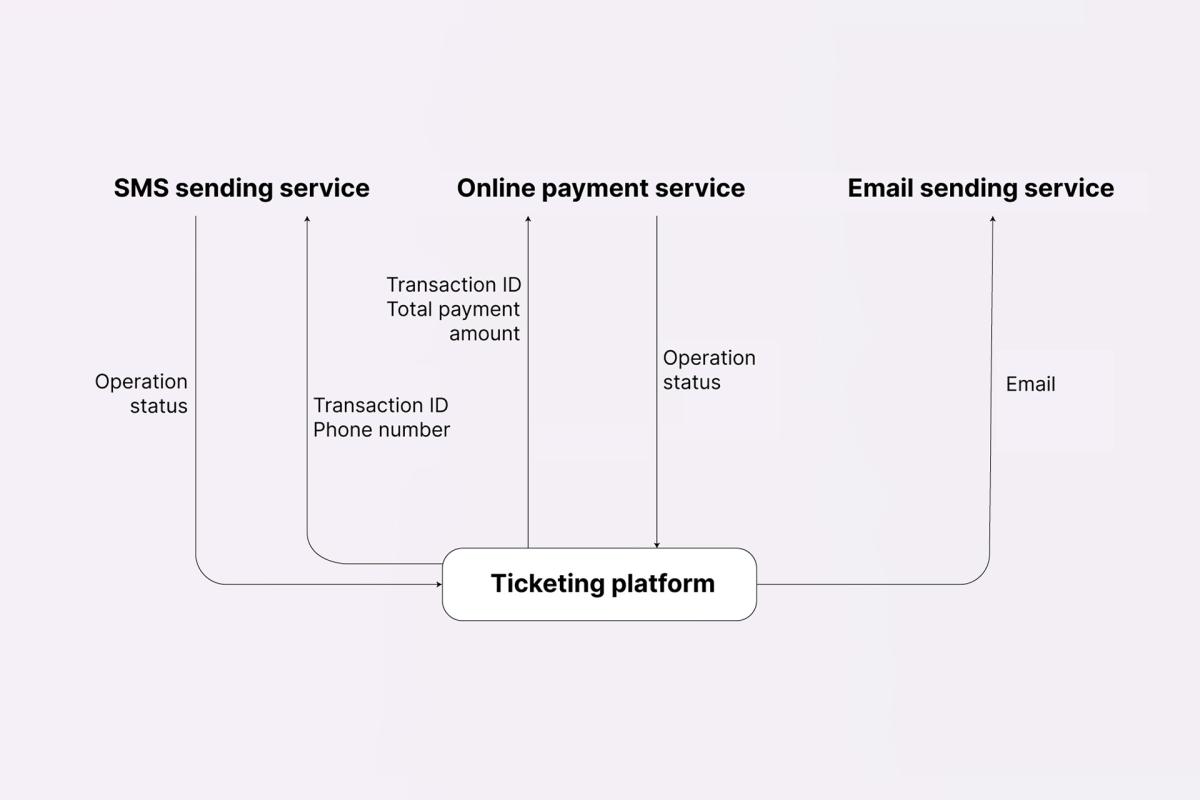
This is a simplified, high-level version of the diagram – it is enough to show all interactions and data flows between different systems. Any further decomposition depends on the project and your role within it: if needed, you can make it extremely detailed and list every attribute, or define every parameter that is included in the exchanges between each pair of services.
User interface
Apart from third-party services, a product also interacts with its end-users – through UI.
Here’s a short checklist of items that you should verify at this stage:
- Are all design elements properly described and implemented?
- What are the requirements regarding fonts and colour schemes?
- What are screen size, orientation, resolution restrictions?
- Are there any shortcuts/key combinations?
- Is the system accessible to all users? (Evaluate the product’s accessibility: colour contrast ratios, alternative text for images, consistent layout, etc.)
- What input control elements does a screen contain?
- Are all controls arranged in a way that complies with the current UI standards?
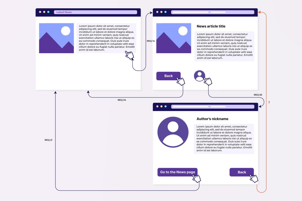
- Do all screens, forms, and interactions between them have a description? (They can also be represented in the form of a map, as in the picture below – it’s pretty convenient to use as every transition can be accompanied with a link to the corresponding requirement, or a “?” note if none have been found in the specification.)
All of the models explored in this part can prove really useful during the QA process: they allow you to determine what elements the system you’re testing consists of, figure out what is missing, and quickly identify the source of data that is being processed in any particular operation.
And, as mentioned in the very beginning, the second part of the article will expand more on the topic of a product’s qualities and characteristics.